Illustrator question (1 Viewer)

deeoohhgee

High Hand
Joined
Feb 25, 2021
Messages
89
Reaction score
110
Location
San Antonio, TX
have sort of a couple technical questions related to AI & designing a chip ...

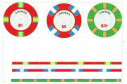
i've gotten some assistance with a template to start from, and i have noticed that the edge spotting is shaped in & the chip background is cut out to fit. i'll call this approach "pathing" since it's clearly all about manipulating paths to fit together, etc on the same layer. My question about this is: why do it it this way? My initial approach was to create a circle and layer the edge spot shapes onto the chip's background color. i'll call this approach "layering." Is pathing preferred because AI is vectorized? and if there are layers present the printing tool would try to overlay colors messing things up?
 
my other question ... i see all the work done on creating the rolling edge spot design, unraveling the circumference of the chip edge ... i understand that work. My question is if there is any way within AI to "link" that to the chipface to ensure alignment, or if that's something the manufacturer does?
 
What you describe as "pathing" is a clipping mask. Menu>Object>Clipping Mask>Make (or release)...or ctrl+7 (alt+ctrl+7)
Think of a clipping mask for chip design as a large piece of white paper with a 39mm hole in the middle. You can organize all your art underneath, but only see what will print on the chip.
There's two reasons why clipping masks are great here. First, you're not stuck making your art fit the curve of the chip. you can have any art extend beyond the edge without worry, as the mask will hide anything that extends beyond the edge.
Secondly, it's great for the printer because it has "bleed". Bleed is the extra art needed beyond the edge of the chip. Otherwise, if your art is an EXACT 39mm circle, it will never align perfectly on a 39mm chip. So, the printer will be forced to enlarge the art slightly so that even a minor misalignment during printing is not noticed. By having the extra art below the clipping mask, the printer is not required to enlarge your art.

Not sure what you mean about linking the rolling edge to the face. Creating an accurate rolling edge from scratch is a bit of a process. It involves either a fair amount of math...or by creating the chip, then exploding all the paths and measuring the length of each one.
That's why those templates, especially the one from @eightyWon are so valuable.
 
thanks for the input ... i'm (obviously) still new to AI & am learning ... trying to balance producing something against not messing up. What i meant about "linking" the rolling edge to the chipface: assume i've done my maths right about unrolling the edge of the chip ... how does the printer know "where to start" on the edge in relation to the chipface? i hope that's a little clearer
 
You can always give the chipmaker instructions on where to start the rolling edge. Sometimes it’s easy to tell but it’s still safer to be explicit. Some designers always start their rolling edge at the same location/direction, e.g., 12 o’clock or 6 o’clock and clockwise. Some will generally do that unless it splits an edge spot in which case they will start the the edge stripe at a spot.

For myself, since I add ripples to the edges of the spots to simulate compressed clay, I actually prefer to start in the middle of a spot, so that it’s a clean color down the vertical of the stripe.
 
thanks for the input ... i'm (obviously) still new to AI & am learning ... trying to balance producing something against not messing up. What i meant about "linking" the rolling edge to the chipface: assume i've done my maths right about unrolling the edge of the chip ... how does the printer know "where to start" on the edge in relation to the chipface? i hope that's a little clearer
I used to set it up where the rolling edge started at the very top, 12 o'clock position. However , that often meant splitting an edgespot in half to make that work.

More recently, I'm centering edgespots within the rolling edge frame, and yes, the printer will adjust as necessary. One thing they will also do for you is reverse the edgespot pattern for the other side of the chip as necessary for chips like these:
edgespot-reverse.jpg

You only need to provide side A.
 
You can also often identify where an edge strip starts/stops—there’ll be a vertical line that’s slightly darker due to the starting/stopping points overlapping slightly. I’ve actually been starting my edge strips at 6 o’clock just to “hide” that when someone picks up a chip to examine it “right side up”.

Though if you stack your chips with the “correct orientation” from your perspective, then that edge stripe overlap will be facing you, which you may prefer over it facing other people, if anyone actually cares about that.
This is interesting and I never really looked at it before. Since I have been centering all my spots, I left it to Tina to choose where the seam will be.
Of all the samples I have, she has put seam at the 2, 4 and 8 o'clock positions, with the VAST majority of them at 8 o'clock.
 
What you describe as "pathing" is a clipping mask. Menu>Object>Clipping Mask>Make (or release)...or ctrl+7 (alt+ctrl+7)
Think of a clipping mask for chip design as a large piece of white paper with a 39mm hole in the middle. You can organize all your art underneath, but only see what will print on the chip.
There's two reasons why clipping masks are great here. First, you're not stuck making your art fit the curve of the chip. you can have any art extend beyond the edge without worry, as the mask will hide anything that extends beyond the edge.
Secondly, it's great for the printer because it has "bleed". Bleed is the extra art needed beyond the edge of the chip. Otherwise, if your art is an EXACT 39mm circle, it will never align perfectly on a 39mm chip. So, the printer will be forced to enlarge the art slightly so that even a minor misalignment during printing is not noticed. By having the extra art below the clipping mask, the printer is not required to enlarge your art.

Not sure what you mean about linking the rolling edge to the face. Creating an accurate rolling edge from scratch is a bit of a process. It involves either a fair amount of math...or by creating the chip, then exploding all the paths and measuring the length of each one.
That's why those templates, especially the one from @eightyWon are so valuable.
i'll just be "explicit" ... the
 
i was going to give an Illustrator file that had explicit examples of the methods i'm referring to. But alas, i can't upload a .ai file ... i guess it's a nono.
 
i was going to give an Illustrator file that had explicit examples of the methods i'm referring to. But alas, i can't upload a .ai file ... i guess it's a nono.
You can upload the .ai file to a file host like Google Drive or OneDrive and share the link.
 
so i'll attach a screenshot from within AI ...

chips are of different design "modes" to show stuff ...

the rightmost chip has all the outlines of the "pathing" i'm talking about, AND i really spaghettied it worse by overlaying some thing just by rotation
the middle chip is the same approach, but i was more careful of respecting all the "pathing" that was in the template.
the leftmost chip i did myself with the "layering" method as i call it ... so under the stipes is a base layer red circle ... which is NOT the case when one uses "pathing."

This is where my question about the vectorized notion of the AI files comes into play ... if i use the layering, will the printer try to print the red underneath the blue & yellow stripes, thus bleeding two colors onto each other?
 

Attachments

  • TwoNickelsAndOneQuarter.png
    TwoNickelsAndOneQuarter.png
    162.7 KB · Views: 49
What you seen on-screen will print that way. However, I generally try to tidy up art so that something that is there, but isnt supposed to be, is removed. I'd remove the extra green edgespots you have on the green chip that are also green, just to make double-sure that the edges never appear. You can either use the direct selection tool (A on keyboard) and then delete them... or double click the chip and go into isolation mode (may need to double click multiple times to get deep enough) and delete them from there.
Instead of making all the chips/edgespots yourself, I highly recommend using the Illustrator template for most chip/edgespot designs from this thread:
https://www.pokerchipforum.com/thre...phics-useful-for-tina-anita-cards-mold.81302/

If you need any specific chip patterns that are not in that template, PM me, I have a few different ones I've created.
 
" ...tidy up art so that something that is there, but isnt supposed to be, is removed."
This is •precisely• what i meant as the difference between "pathing" and "layering." It seems you're saying that pathing is the better approach. Once i have layered edge spots onto a circle (assume i've done it properly), how do i "cut out the spots from the circle?" so that, as you say, the color under the edge spot which isn't supposed to be there is cut out?
 
This is •precisely• what i meant as the difference between "pathing" and "layering." It seems you're saying that pathing is the better approach. Once i have layered edge spots onto a circle (assume i've done it properly), how do i "cut out the spots from the circle?" so that, as you say, the color under the edge spot which isn't supposed to be there is cut out?
& then even more to the point ... do i then have to leave an annular cut out in the center of the chip where the inlay is?
 
I would be careful of using terms like pathing and layering, because they mean different things within the app and can get you (and me :ROFL: :ROFLMAO:) confused...
Layers are something different and you should be using them as well.
First off, there's no reason to cut anything out. placing one item on top of another is perfectly fine, the underlying color or items will not "show through".

Speaking of layers, when designing, I put the base chip with edgespots on one layer (using the layer window) and I put the inlay on another layer. I often will put the denomination on a 3rd layer, so I can isolate and edit easier. What makes this so powerfull is you can hide the inlay layer to work on the base chip if you desire. And you dont need to worry about the items on a lower layer showing through to the upper layers...it will print as you see it.

I can send you a sample chip set up the way I do it, if you like, so you can take it for a "test drive". PM me your email address if you want.
 

Create an account or login to comment

You must be a member in order to leave a comment

Create account

Create an account and join our community. It's easy!

Log in

Already have an account? Log in here.

Back
Top Bottom