Adding hardware to step up our slot machine game! (1 Viewer)

Test: Drilling holes in the acrylic

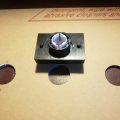
The larger IGT buttons have small pegs built in underneath. When you install the buttons, these pegs go into holes to hold the buttons in place and keep them from spinning,
Button Top Peg.jpg
Button bottom peg.jpg

Larger IGT buttons have pegs on the bottom to keep them from spinning
You can see them at 3 and 9 o'clock in the photo at right. I'll need to drill
two small holes to the left and right of the center holes to put these in.

This morning, I used one of the samples of 1/8" acrylic to see if I could drill a hole in it without cracking it. We'll need four for the larger buttons, and possibly on each corner to install the panel.

20231227_122845.jpg
20231227_122940.jpg

I used the black acrylic sample Tapp Plastics sent and the new 1/8" drill bit. You place a piece of scrap wood below and on top of the acrylic and clamp it tightly. Drill on your mark, starting slow and increasing, and it will go right through. No problem! The hole came out perfectly round and exactly where I wanted it.
 

Attachments

  • 20231227_132641.jpg
    20231227_132641.jpg
    128.2 KB · Views: 23
Last edited:
Update: Drilled all the holes in the control panel today using a 1/4" drill bit used to cut glass. After the holes were drilled, I was finally able to peel the paper off the acrylic. The panel is translucent, so lights under the panel and decals using transparent labels are options.

20231228_150152.jpg
20231228_145755.jpg

Left: The acrylic panel with all the holes (finally) cut, including an error that gets hidden by the button. Right: A quick test fit
of all the buttons, just to make sure. The area to the right of the "Play Max Credits" button is where the voucher will come out
onto the control panel (and hopefully go in, if the TITO printer works out.)
Next step: A simple wooden frame that fits under the panel, then some black molding around the outside of the panel covering the edge, and we'll be ready to wire it up.


Spent some time wiring the IGT buttons So far, lights inside the buttons are wired, connected and working. They look great, but the photos make them look really bright. (They're bright, but not as bright as they look here.)

Board Wired.jpg
20231231_164939.jpg
20231231_165300.jpg

The black wire is ground and is chained to the negative terminals on each button and connected to one of two ground wires in the controller.
The white wire is 5-volt and is chained to the positive terminals on each button and connected to one of two "5V" wires in the controller.
Plug the controller into a USB port on the laptop, and everything lights up.

I need to get more connectors to wire two more connections to each button to trigger each button command.
 
Last edited:
Stayed up late last night wiring the action portion of each button. Between the "light" side and "action" side of each button, it's a total of 20 connections from the controller to the five buttons.

Yellow wires are chained ground wires for the actions. Black wires connect the blue portion of the plugs to the controller and tell the software to do the action when you press the button.

Alligator clips are attached to the "service" button to add 1 credit each time the "service" button is pressed. That can be quickly disconnected when I don't want to use it. (An on/off switch wired in to do this didn't work, so I nixed it.) Color-coding the ground wires makes it a little easier to figure out what something does if it becomes disconnected.

All the buttons are wired, stable, lit up and working. Each button triggers the expected action on the slot machine.

Now I just have to figure out why the receipt printer stopped working when the board is plugged in. (That may be unrelated to the IGT buttons.)

UPDATE: A check box that sends the receipt to the printer was accidentally unchecked while setting up the printer. The box is checked, and the printer works. When you hit the "CASH OUT" IGT button, it empties the player credits from the machine and automatically sends a cash out voucher to the printer.


20240103_061309.jpg
 
Last edited:
The next step...

The obvious next step is to transfer the side outline of the machine onto plywood at 100 percent size and (carefully) cut it out two copies with a jigsaw. I'm basically building the slot machine cabinet around the monitor, printer and control panel.

Side enhanced.png

I'm holding off on this step until we know which printer will go into the machine. The location and angle of the bezel that guides the voucher out to the player will be different for each of the printers, and the amount and location of space for the printer inside the cabinet is also different. The printers are shaped differently.

When I know which printer will go inside, I can draw and cut the sides, then make sure the two sides match each other exactly. For everything to be level, the two sides will need to be a perfect match. (Cutting, plaining and sanding will no doubt be involved.)
 
Last edited:

Create an account or login to comment

You must be a member in order to leave a comment

Create account

Create an account and join our community. It's easy!

Log in

Already have an account? Log in here.

Back
Top Bottom