
Re-Molding (49 Viewers)

Cratty

Flush
Supporter
Joined
Mar 17, 2024
Messages
2,098
Reaction score
12,638
Rewards
64
Location
Michigan
Keep thinking about this given peoples experience w/ flattening chips (creating donuts, double molds), etc... feels like there's an opportunity to "re-mold" chips - i.e. put in a worn THC chip into a tool and regain sharp edges/texture/etc (with materials coming from the center/recess area of the chip).

Assuming this won't go anywhere, but wanted to at least put on paper so I can be told this is a fools errand or incase someone out there has the means/desire to try this. lol
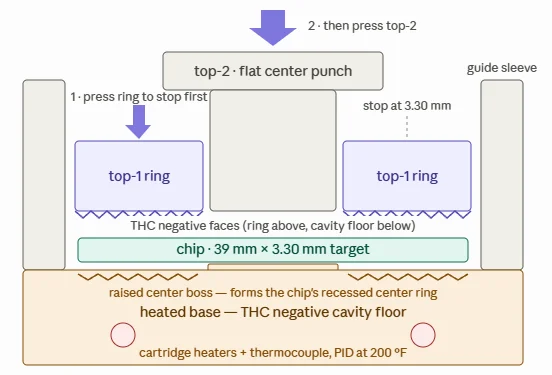
1783952531182.webp


Concept
A three-piece die set consisting of:
  1. Heated base — aluminum or steel block with a 39.3mm chip pocket. The pocket floor carries the negative of the mold pattern for the bottom face.
  2. Top-1: floating ring — slides in a guide sleeve, carries the pattern negative and rim profile for the top face outer band. This seats first.
  3. Top-2: flat center punch — slides inside the ring, could also be textured.
Force comes from a 1-ton arbor press. My gut says ~500–1,500 lbf should be more than sufficient.

Cycle
Soak the chip in the closed cavity 3–5 min at ~180–200°F → seat the ring (~500 lbf) → drive the center punch to the hard stop, hold 2 min, and cool the whole clamped stack before release.

Biggest issues I see are:
  1. Slow.. could theoretically expand the setup to do multiple chips at a time, but hard given how these would be pressed, as well as cooling time to make sure they don't re-warp.
  2. Flow... would just have to test and see to determine if the amount of heat and pressure is OK
  3. Cost.. Probably could prototype a proof of concept relatively cheaply, but obviously would be relatively expensive ($1-$2k I'd assume) to get the 3D chip scans, CNC'd tools, etc.
 
If you can remold chips then why not just make new chips
Edge spots, material flow, lathing, sourcing of raw materials/mixing, more pressure/heat required. Just a much larger overall investment as well as unknown on material compositions.
 
Keep thinking about this given peoples experience w/ flattening chips (creating donuts, double molds), etc... feels like there's an opportunity to "re-mold" chips - i.e. put in a worn THC chip into a tool and regain sharp edges/texture/etc (with materials coming from the center/recess area of the chip).

Assuming this won't go anywhere, but wanted to at least put on paper so I can be told this is a fools errand or incase someone out there has the means/desire to try this. lol

View attachment 1701778

Concept
A three-piece die set consisting of:
  1. Heated base — aluminum or steel block with a 39.3mm chip pocket. The pocket floor carries the negative of the mold pattern for the bottom face.
  2. Top-1: floating ring — slides in a guide sleeve, carries the pattern negative and rim profile for the top face outer band. This seats first.
  3. Top-2: flat center punch — slides inside the ring, could also be textured.
Force comes from a 1-ton arbor press. My gut says ~500–1,500 lbf should be more than sufficient.

Cycle
Soak the chip in the closed cavity 3–5 min at ~180–200°F → seat the ring (~500 lbf) → drive the center punch to the hard stop, hold 2 min, and cool the whole clamped stack before release.

Biggest issues I see are:
  1. Slow.. could theoretically expand the setup to do multiple chips at a time, but hard given how these would be pressed, as well as cooling time to make sure they don't re-warp.
  2. Flow... would just have to test and see to determine if the amount of heat and pressure is OK
  3. Cost.. Probably could prototype a proof of concept relatively cheaply, but obviously would be relatively expensive ($1-$2k I'd assume) to get the 3D chip scans, CNC'd tools, etc.
Save money on racks because now you can put 25 in a barrel
 
It might work. Worthy of some testing - perhaps a hand job as a proof of concept. A series of tests are needed long before someone builds a fancy production rig.

Likely not cost effective, but who can say with our crowd? Restoring chips back to uncirculated could be the next new thing. Look at what we spend to mill and relable chips.

Interesting -=- DrStrange
 
Save money on racks because now you can put 25 in a barrel
If we cap the tool at 3.3mm thickness (as well as diameter at 39-39.3), and let the materials come from the inner ring (flow out to the outer ring to fill any issues), I assume it would prevent any thickness issues like that.
 
Last edited:
If we are assuming this is plausable, interesting theory.

How much material is missing from a "bike tire" chip? If you maintained the original thickness, what diameter chip could you end up with? 38mm, 37mm less?

Obviously it would vary from each amount of chip wear. But using a fair extrapilation, what would we expect?
 
If we are assuming this is plausable, interesting theory.

How much material is missing from a "bike tire" chip? If you maintained the original thickness, what diameter chip could you end up with? 38mm, 37mm less?

Obviously it would vary from each amount of chip wear. But using a fair extrapilation, what would we expect?
My view is all excess materials would come out from the center of the chip (recessed area), and protect for the 39mm outer diameter and 3.3mm thickness. That said, assume some chips like major bike tires would not have enough materials in the middle recess area to do this.

Crude mockup/example:

1783954997784.webp
 
How much material is missing from a "bike tire" chip? If you maintained the original thickness, what diameter chip could you end up with? 38mm, 37mm less?

Obviously it would vary from each amount of chip wear. But using a fair extrapilation, what would we expect?
36mm antique chips are about to become vogue
 
I evaluated my outpost $1 chips, at the time the most worn chip in my collection. The bicycle tires were 5% thinner and 3% thinner than an uncirculated chip from the same card room.

Going from 39mm to 38mm is a 5% reduction in volume. That will be quite the trick to accomplish. It is one thing to remold only on the vertical axis. Quite another to redistribute the materials in three dimensions. Doing that while keeping the edge spots in good condition seems more than a little ambitious.
 
I evaluated my outpost $1 chips, at the time the most worn chip in my collection. The bicycle tires were 5% thinner and 3% thinner than an uncirculated chip from the same card room.

Going from 39mm to 38mm is a 5% reduction in volume. That will be quite the trick to accomplish. It is one thing to remold only on the vertical axis. Quite another to redistribute the materials in three dimensions. Doing that while keeping the edge spots in good condition seems more than a little ambitious.
Yes - diameter would need to stay at 39-39.3mm or whatever the standard is for the mold. No way to make a tool either to make a 39mm fit into 38mm anyway without another first/crude compression step.

The only other area to save or redistribute material from other than the inner recessed area would likely be a slight amount from the mold indentations themselves (e.g. if a THC impression is .4mm deep, make it .6mm deep. Not sure if that would be desired, but might be OK to do something there).
 
Last edited:
It might work. Worthy of some testing - perhaps a hand job as a proof of concept. A series of tests are needed long before someone builds a fancy production rig.

Likely not cost effective, but who can say with our crowd? Restoring chips back to uncirculated could be the next new thing. Look at what we spend to mill and relable chips.

Interesting -=- DrStrange
I don’t have the energy to get this into the out of context thread…but someone else probably does.
 
Doesn’t rivieraDanny offer this service? I have no idea if the method is that same, but edge-conditioning is being done. (And, predictably, I’m opposed to it. Whether or not a chip will stand on edge is an age-old standard for evaluating chip condition, and this messes with that.)
 
Doesn’t rivieraDanny offer this service? I have no idea if the method is that same, but edge-conditioning is being done. (And, predictably, I’m opposed to it. Whether or not a chip will stand on edge is an age-old standard for evaluating chip condition, and this messes with that.)
Edge conditioning removes more material, this would redistribute and not lose additional.
 
I feel like there would have to be some post compression edge conditioning, anyway.
Possibly, my thought was you could design the tool such that there’s no flow outside and flashing created, but would require some pretty tight tolerances between tool pieces. Not sure how feasible or if that would create an issue or not with actual pressing, but probably a fair concern in realism or tooling expense. If there was some flashing though because tolerances couldn’t control, I would think it would not be on the chip edge but more coming out of the top/sides, and hopefully thin enough that it would just break off without leaving a remnant.
 
Edge conditioning removes more material, this would redistribute and not lose additional.
Shit, sorry, I didn’t read your method (assuming it was something similar to Danny’s secret method.) This seems like science fiction to me, but I’m all in favor of science, for science!
 
Shit, sorry, I didn’t read your method (assuming it was something similar to Danny’s secret method.) This seems like science fiction to me, but I’m all in favor of science, for science!
It’s still a good point, as some could potentially use something like this and pass as newer than reality, where issue would be lower chip weight and some removed thickness of the recessed area (which may or may not be very noticeable). Edge conditioning at least is somewhat clear in comparing chips given diameter difference.

Well.. at this point I think we’ve hashed out the what-ifs enough. Maybe someday I or someone else will try to take some experimentation to prove out the concept.

Ultimately the thought here stemmed from how we might “flatten” some of the inlay area on cancellation stamped chips like @Rieguy’s Grand Casinos, but evolved into a larger potential. Probably a fools errand across the board.
 
i feel like tolerances that tight could restrict air movement enough to stop the chip from filling the cavity evenly. this is kind of a neat idea, though i would worry about the integrity of the recessed area depending on how material had to move
 
Possibly, my thought was you could design the tool such that there’s no flow outside and flashing created, but would require some pretty tight tolerances between tool pieces. Not sure how feasible or if that would create an issue or not with actual pressing, but probably a fair concern in realism or tooling expense. If there was some flashing though because tolerances couldn’t control, I would think it would not be on the chip edge but more coming out of the top/sides, and hopefully thin enough that it would just break off without leaving a remnant.
If you are melting shit, just throw more material in there from the get go.

Make one chip out of two
 
If you are melting shit, just throw more material in there from the get go.

Make one chip out of two
This is what I thought. If you can take two bike tires and make a new sharp chip That’d be super.
 
You could 3D print the tooling jig using Polycarbonate filament; can withstand both the heat and the pressure you’re talking about while being affordable enough to have 20 of the setup to swap out while cooling in the rig. By the time 1 is cooled enough (??) 20 is just finishing pressing. Not sure on the timing, but given what you’re talking about that would be both economical and hurry the process along.
 
This is what I thought. If you can take two bike tires and make a new sharp chip That’d be super.
Yeah, might work for solids, but not so much for chips with edge spots or inlays. Could possibly add a bit of a broken chips/shards in places though.

That said, I assume just changing the shape of an existing single chip is easier and could be done likely at lower temps/pressure. I suspect you’d have to significantly bump temp/pressure to get two pieces to come together. I’d be concerned that any added bits would just come break off easily or have a witness line.
 
Last edited:

Create an account or login to comment

You must be a member in order to leave a comment

Create account

Create an account and join our community. It's easy!

Log in

Already have an account? Log in here.

Back
Top Bottom