-
PCF is an eBay Partner. If you make a purchase through one of our links, we may earn a commission at no extra cost to you. Thank you for your support!
You are using an out of date browser. It may not display this or other websites correctly.
You should upgrade or use an alternative browser.
You should upgrade or use an alternative browser.
Experimenting with a DIY RFID Table and Broadcast Overlay (2 Viewers)
- Thread starter eightyWon
- Start date
eightyWon
Straight
eightyWon
Straight
v1 of the RFID board came today. Happy to report no smoking and my PC recognized it immediately upon plugging it in.
I've loaded some basic test firmware and have connected the board to my wifi and blinked the LEDs. It honestly feels like a smashing success so far!

I'm working on cusotm firmware now to test the RFID capabilities. I haven't found any great examples or libraries yet for the esp32/st25r95 combo so this part will be a little slow going.
I've still been working on v2 of the board and also the frontend in parallel with all this so there's some progress being made there, too.
I'm sure I'll have more pics or video of v1 doing it's thing at some point.
I've loaded some basic test firmware and have connected the board to my wifi and blinked the LEDs. It honestly feels like a smashing success so far!
I'm working on cusotm firmware now to test the RFID capabilities. I haven't found any great examples or libraries yet for the esp32/st25r95 combo so this part will be a little slow going.
I've still been working on v2 of the board and also the frontend in parallel with all this so there's some progress being made there, too.
I'm sure I'll have more pics or video of v1 doing it's thing at some point.
LaBestiole
High Hand
EightyWon, as you know, i'm working on a similar project with some retrogaming theme. For the sake of discussion and to partially answer to your post, i thought it would be useful to share the current mockup of the GUI i'm currently implementing (used BGinGa idea for the name but i will take it out if asked ofc, as i was answered for your projectStill doing stuff while I wait for a few of the components to come in at the fab shop (might still be a few weeks).
I've started researching and designing v2 of the rfid reader. Early stages but going well. I'm taking extra time to do it right this time in various ways.
I've also started working on a redesign of the frontend in go instead of node/angular as mentioned before. Making good progress here, too.
Been spending some time considering from a UX perspective how everything will flow and work.
Given you've got the hardware installed in your table and you're plugging it in for the first time, what needs to be configured and how does that work and look?
When you're ready to broadcast a game, how does connecting the hardware to the frontend work and look?
How about feed security (outside of obvious SSL/TLS but operationally)?
Lots of things I'm brainstorming on right now in terms of the design of the whole package.
I would love to hear what your ideal solutions look like as well as what features they include.
 ). So the idea is to run this on a computer. I might develop something for the dealer in the future, i'm currently thinking of a stream deck, but i think the dealer already has to be 100% focus on the action going, so his input for the rfid system should be minimal.
I will use antennas for an rfid dealer button to track the action / position of players. I'll go for a 6-players table, with central positionned, board-antenna integrated pcb. Each antenna has its own transceiver and is connected via SPI to the mainboard. That will handle the problem of muxing RF signals and allow me to have custom antennas for each role (hole cards, board, much, dealer button all require different sizes, some do not require anti-collision,...).
Again, thx for the shared informations/updates.
Last edited:
eightyWon
Straight
Man, it's been a dreadful few days but this morning I jumped out of my seat when I got the bolded lines from the logging output of my firmware:
From the st25r95 datasheet:
So, after days of trying and troubleshooting and a comedy of errors including a defective antenna, v1 of my board is finally reading an RFID tag!
The feeling of that moment when something you've been working toward/struggling with seemingly forever finally works is so good. When I saw the resp code finally change from a wall of 0x87s (no tag detected, basically) to a 0x80... better than just about anything.
-
So the bad news is antenna tuning will indeed be a new issue to learn/solve because right now the RFID tag must be fully touching the antenna and even in the perfect orientation for us to detect/read the tag. From everything I've learned so far, this can be solved by fine tuning the antenna matching circuit and the antenna design (right now I'm actually just using one of the Pepper C1 antennas so, someone else's design).
There's also a ton more work to do on the firmware. It's very sloppy right now and literally just the bare minimum code to validate that the hardware works.
Plus all the other outstanding work.
But for right now, HOLY SHIT IT WORKS (kinda)")
12:07:31.509 -> ets Jun 8 2016 00:22:57
12:07:31.509 ->
12:07:31.509 -> rst:0x1 (POWERON_RESET),boot:0x13 (SPI_FAST_FLASH_BOOT)
12:07:31.509 -> configsip: 0, SPIWP:0xee
12:07:31.509 -> clk_drv:0x00,q_drv:0x00,d_drv:0x00,cs0_drv:0x00,hd_drv:0x00,wp_drv:0x00
12:07:31.509 -> mode: DIO, clock div:1
12:07:31.509 -> load:0x3fff0018,len:4
12:07:31.509 -> load:0x3fff001c,len:1216
12:07:31.509 -> ho 0 tail 12 room 4
12:07:31.509 -> load:0x40078000,len:10944
12:07:31.509 -> load:0x40080400,len:6388
12:07:31.555 -> entry 0x400806b4
12:07:31.877 -> Connecting to WiFi ....192.168.1.69 (nice)
12:07:33.862 -> RRSI: -58
12:07:33.862 -> trying to put the st25r95 in SPI mode
12:07:34.001 -> IDN_Command
12:07:34.001 -> Response Code 0 Data len F
12:07:34.001 -> DEVICE ID: NFC FS2JAST4 ROM CRC: 2ACE
12:07:35.012 -> setting protocol
12:07:35.012 -> 0
12:07:35.012 -> F
12:07:35.060 -> Response Code 0 Data len 0
12:07:35.060 -> PROTOCOL SET-
12:07:35.060 -> 0
12:07:35.060 -> 0
12:07:35.060 -> Response Code 80 Data len 5
12:07:35.570 -> Response Code 87 Data len 0
12:07:36.126 -> Response Code 80 Data len 5
12:07:36.635 -> Response Code 87 Data len 0
12:07:37.196 -> Response Code 80 Data len 5
12:07:37.705 -> Response Code 87 Data len 0
12:07:38.214 -> Response Code 80 Data len 5
12:07:38.766 -> Response Code 87 Data len 0
From the st25r95 datasheet:
0x80 EFrameRecvOK = Frame correctly received (additionally see CRC/Parity information)
...
0x87 EFrameWaitTOut = Frame wait time out (no valid reception)
So, after days of trying and troubleshooting and a comedy of errors including a defective antenna, v1 of my board is finally reading an RFID tag!
The feeling of that moment when something you've been working toward/struggling with seemingly forever finally works is so good. When I saw the resp code finally change from a wall of 0x87s (no tag detected, basically) to a 0x80... better than just about anything.
-
So the bad news is antenna tuning will indeed be a new issue to learn/solve because right now the RFID tag must be fully touching the antenna and even in the perfect orientation for us to detect/read the tag. From everything I've learned so far, this can be solved by fine tuning the antenna matching circuit and the antenna design (right now I'm actually just using one of the Pepper C1 antennas so, someone else's design).
There's also a ton more work to do on the firmware. It's very sloppy right now and literally just the bare minimum code to validate that the hardware works.
Plus all the other outstanding work.
But for right now, HOLY SHIT IT WORKS (kinda)
eightyWon
Straight
Small bit of good news. Once I had the firmware detecting tags, I did some more testing with different tags. I'm getting about 2.5" of read distance with the RFID deck of cards I bought from AliExpress so my design isn't actually that far off.
As compared to the Pepper C1 (about 4"), I'm still getting less read distance with my board but not terribly so.
So, optimizations to be made still to the antenna circuit but I'm really pleased at this point.
I think I'm going to put most of my focus now into v2 of the board and multiplexing because once that's sent into production, I'll naturally have some time to work on the software side.
eightyWon
Straight
LaBestiole
High Hand
It is unclear to me why you would need to redesign your antennas. In your case, considering you are using external antennas with a cable (for the eccel antennas, looks like they have some twisted pair for the differential signal and a ground). If eccel did a good job, i would assume the impedance of the load matches the characteristic impedance of the cable for max power transfer. So what i'm saying is that the antennas are fine and you should probably adapt the matching circuit on your main board that comes right after the EMC filter. I don't know, maybe copying the pepper c1 shematic and removing the multiplexer changed the matching for the part before the cable ?
For the antenna design, i saw somewhere that it's best to avoid right angles in the corners. No idea if it's critical x)
Can you put your antenna kicad files on your git? Might save me some hours :-D
For the antenna design, i saw somewhere that it's best to avoid right angles in the corners. No idea if it's critical x)
Can you put your antenna kicad files on your git? Might save me some hours :-D
eightyWon
Straight
A few different reasons.It is unclear to me why you would need to redesign your antennas.
The biggest reason is so I can eventually offer production-ready files for both the reader and the antennas. With that, no one has to rely on commercial products that may or may not be available in the future. That supports one of my original main project goals which is a complete package from soup to nuts and all the info anyone would need to implement it.
A more immediate reason is for testing and tinkering. With this first antenna design, as I mentioned, I made the component packages a little larger so I could easily hand-solder them with the idea of tweaking certain values and observing the result.
Another reason is that I wanted to modify the footprint slightly. The largest Eccel antenna I own (and the largest they make, last time I looked) is 80x80 which isn't wide enough for two cards side-by-side. Yes, the 80x80 antenna will generally still read two cards side-by-side, but reception gets worse as you deviate more from the center of the antenna. I want to see how the larger antenna footprint behaves with relation to RFID playing cards.
Also, if I can design usable antennas, I think they'll be less expensive to produce than what the commercial versions cost. Not a huge difference or deal, but when you're using 10+ for a table, cheaper is better.
Finally, for fun

Yeah, I wish I'd radiused the trace corners a little more. They are slightly radiused, but I think I should have gone more.For the antenna design, i saw somewhere that it's best to avoid right angles in the corners. No idea if it's critical x)
From the little I've read, right angles should generally be avoided with traces but I think it only really starts to become critical at higher frequencies than what we're dealing with. I hope. We'll see.
Can you put your antenna kicad files on your git? Might save me some hours :-D
I do intend to make everything public on github eventually. I'm not sure I'm quite ready yet but IM me if there's some specific stuff you want. As for the antenna design, I really just tried to follow the PN5180 design guide doc. I'm really not nearly smart enough to reinvent the wheel.
eightyWon
Straight
DHL from China today:


Pleased with the result. Hope to solder one up in the next few nights and test em out!
Pleased with the result. Hope to solder one up in the next few nights and test em out!
eightyWon
Straight
I finally had a few minutes this morning during a work call to solder some 0 ohm resistors on to one of the new antenna's matching circuits. This basically amounts to no matching at all on the antenna side, just a coil.
Then I did some testing (green light on the board means power and connected to wifi, blue flashing light on the board means we're reading an RFID tag from the field):
Note, this is with 100% of our home-grown hardware and software now - nothing commercial or from a pre-existing solution used in the making of this video. That's HUGE imo.
As you can see from the video we're getting about 1-1.5" of reception without any antenna side tuning which ain't bad!
I've actually been thinking that leaving the antennas slightly detuned might be a good idea anyway so that we're not accidentally reading cards that aren't supposed to be read at a given position e.g. a player's card slides near another player's antenna - with good tuning we may read it from up to 4-6" and we don't want to. If read distance is limited to 1-2", the chance of false reads I think would be much lower?
LaBestiole
High Hand
I think ideally we want to keep a good tuning. From what i understand, if we want lower detection distance, we can lower the Q factor and get a more robust system to detuning, which might occur if people put their phones or any metallic thing on the playing field. That being said, reaching 1.5'' is really great at this stage. Also i'm not sure if we really need a matching circuit at all on the antenna side. I don't see what prevents us from considering the antenna and its cable as one load and only put a matching circuit on the main board ? I don't really know for your transceiver, but i work with the PN5180 and its datasheet recommends a 20 ohm load impedance (source impedance from transceiver is around 3 Ohms), so there is no real "impedance matching" anyway. Actually real matching would burn the transceiver :-D
Good luck and have fun with Smith charts
Good luck and have fun with Smith charts
eightyWon
Straight
I've had other things pulling at my attention recently but I have been working on beta rev2 which is where we'll try to implement support for up to 16 antennas per board.
The schematic for rev2 is tentatively done and I've started working on layout and routing (still very rough):

School starts back up in a few weeks, too, so I should be back to more free Wednesday mornings for this kind of stuff.
The schematic for rev2 is tentatively done and I've started working on layout and routing (still very rough):
School starts back up in a few weeks, too, so I should be back to more free Wednesday mornings for this kind of stuff.
eightyWon
Straight
initial schematic, layout, and routing done. Off for review by the (sometimes) helpful folks at /r/printedcircuitboard
LaBestiole
High Hand
Any reason why you changed the transceiver and finally went for the PN5180? My own initial design was with this chip, and i finally went for the TRF7970A due to a lot of problems once you start the impedance matching work if applied to deported antennas. You went for symetrical or asymetrical design ? What is the voltage range of the analog signal (because your mux is quite sensitive to that from what i see in the datasheet).
LaBestiole
High Hand
Now i understand what you felt. And it feels GREATI finally had a few minutes this morning during a work call to solder some 0 ohm resistors on to one of the new antenna's matching circuits. This basically amounts to no matching at all on the antenna side, just a coil.
Then I did some testing (green light on the board means power and connected to wifi, blue flashing light on the board means we're reading an RFID tag from the field):
Note, this is with 100% of our home-grown hardware and software now - nothing commercial or from a pre-existing solution used in the making of this video. That's HUGE imo.
As you can see from the video we're getting about 1-1.5" of reception without any antenna side tuning which ain't bad!
I've actually been thinking that leaving the antennas slightly detuned might be a good idea anyway so that we're not accidentally reading cards that aren't supposed to be read at a given position e.g. a player's card slides near another player's antenna - with good tuning we may read it from up to 4-6" and we don't want to. If read distance is limited to 1-2", the chance of false reads I think would be much lower?

eightyWon
Straight
I used the PN5180 mainly because it's successfully used in the Pepper C1. I don't understand or know nearly enough theory or have test equipment to stray too far from a known working board and reference designs.Any reason why you changed the transceiver and finally went for the PN5180?
I'd love to know more, especially before I ship this design off to be produced. Will you message in that thread we have going?My own initial design was with this chip, and i finally went for the TRF7970A due to a lot of problems once you start the impedance matching work if applied to deported antennas.
For the multiplexing? I'm following what the C1 did and using differential, if that's what you mean.You went for symetrical or asymetrical design ?
With the non-mux'd setup, ~2v. My design uses the ADG1607 in 5v single supply so signal range vdd-vss (0-~5.5v)What is the voltage range of the analog signal (because your mux is quite sensitive to that from what i see in the datasheet).
Should be fine but

eightyWon
Straight
Awesome! Range looks great, did you tune? What mux are you using?Now i understand what you felt. And it feels GREAT
I love the use of coax. One thing I've noticed is that with an antenna cable too long (~2 meters), I'm no longer able to read tags. Have you tried longer cables yet? I'm sure it's a matching issue for me.
LaBestiole
High Hand
For the symmetrical vs asymmetrical tuning, see "AN11741 - How to design an antenna with DPC". You might wanna read AN11740 aswell. From what i've understood, symmetrical tuning gives you good Q-factor and nice detection distances, but you have to be very careful with antenna tuning because the pn5180 doesn't allow less than 20 Ohm impedance. It becomes susceptible to detuning, that's why they have some integrated feature (called dynamic power control) that limits the current if needed, but you must put the right settings in, and you need a VNA for it... Under 20 Ohms, you would draw too much current with a risk of damaging the component. And from what i've seen on forum, it does happen.
Which is related to the other problem : 20 ohms isn't 50 ohms. Usually, you want to have transmission lines with a charasteristic impedance that matches the impedance of the load. If it is different, then the impedance gets "rotated" on a smith chart around the point of characterstic impedance of your line (which means that, when matched, your point rotates around itself, so basically you don't change the impedance by adding a length of line). I played a lot on will-kelsey.com/smith_chart and had a lot of problems once you want to have deported antennas with the PN5180. When the antenna isn't deported, then the distances are short enough that it doesn't matter. For 1m cable, it does matter.
The mux (RF switch) i use : PE42412A. The reason i took this one is that i wanted 13.56MHz to be in the frequency range of the device.
Haven't tried 2m cables yet but i have 4 cables of this length in the box. I will give it a try soon. :-D
eightyWon
Straight
this ended up just being a soldering mistake on my part. I can still read tags with a 2m cabled antenna, but the read range is reduced some.One thing I've noticed is that with an antenna cable too long (~2 meters), I'm no longer able to read tags. Have you tried longer cables yet? I'm sure it's a matching issue for me.
eightyWon
Straight
v2 (multiplexing) order submitted to the fab

there's two flavors of the v2 PCB, they approach multiplexing differently. One is cheaper to produce and hopefully works
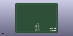
Also a new 90mm x 90mm antenna design
On the software front, I've got the v1 reader reading tags and sending the info via secure websockets to the go server app. Lots more work to do but it's going well
there's two flavors of the v2 PCB, they approach multiplexing differently. One is cheaper to produce and hopefully works
Also a new 90mm x 90mm antenna design
On the software front, I've got the v1 reader reading tags and sending the info via secure websockets to the go server app. Lots more work to do but it's going well
LaBestiole
High Hand
What did you change exactly between the two versions?
Also, i was wondering, did you think already about the camera system? I try to find a cheap, wireless, ideally dual camera system but it’s hard to find.
Good luck
Also, i was wondering, did you think already about the camera system? I try to find a cheap, wireless, ideally dual camera system but it’s hard to find.
Good luck
eightyWon
Straight
one version uses (as originally planned) a couple of ADG1607s to switch the 16 antennas, the other uses 4x NX3L4051 analog switches to do the same.What did you change exactly between the two versions?
I didn't really consider cameras within the scope of my project, preferring to leave that up to the user, mostly because there are plenty of cheap and easy commercial options to do that part and they're basically all supported by whatever broadcast software the user chooses, too. We'll just provide the typical overlay (board, hole cards, odds, positions, player names, etc.), the rest is the easy partAlso, i was wondering, did you think already about the camera system? I try to find a cheap, wireless, ideally dual camera system but it’s hard to find.
LaBestiole
High Hand
I see. I like both of your options for the multiplexing. I'm really curious to see how that unfolds.
Are you still working on an tablet app for the dealer ?
Maybe we could share the "transmission protocol" (i don't know how to call it but you guess what i mean), so that both our system can interact with the same software for the computer part. Here's where i am :
(i realize i need to add poker chips in the video. My bad)
eightyWon
Straight
Looking really good!
I'm curious to see how my multiplexing efforts unfold, too . Likely a few weeks for the hardware to arrive.
I am building a number of things into what I'm calling the "server" software, including an interface for the dealer, one for the "control booth", an admin interface for managing decks/cards, config, etc.
In terms of what the RFID hardware does, I intend to keep it very limited. It'll simply get the UUID from the cards at various positions and transmit those securely to the server. There will be obviously an admin interface there as well to configure things like the websocket connection, maintain the cert chain necessary, etc., but that's it. I intend for the server to do the heavy lifting.
My point there being that in terms of transmitting the data, it'll likely be sending a simple json object with seat/antenna number and UUIDs read at that position (very similar to the info in the serial log in your vid).
I'll be happy to share the server software code (golang) once it's a little further along.
eightyWon
Straight
Oh @LaBestiole, the RFID playing cards you purchased, are the tags 15693 or 14443?
Curious if these a standard the RFID playing cards makers are sticking to or if it varies (meaning the RFID hardware will have to handle multiple tag types - likely).
Curious if these a standard the RFID playing cards makers are sticking to or if it varies (meaning the RFID hardware will have to handle multiple tag types - likely).
LaBestiole
High Hand
I work with 15693 iso cards. I saw cards that run on the 14443 iso. My understanding is that this standard is more for secure cards (for the bank etc) where u want a short distance reading for security reasons. So not what we really want. I remember even seing cards with rfid tags on another lower frequency.
People will have pay attention to what they’re buying as rfid cards.
People will have pay attention to what they’re buying as rfid cards.
eightyWon
Straight
v2 boards are with FedEx. Really hopping I'll have them in hand by the end of the week.
These boards use a different RFID chip (PN5180) than v1 (ST25R95) which means changes to the firmware. I ordered a couple of PN5180 RFID modules off Amazon specifically for developing and testing the firmware while we wait for the v2 boards to arrive.
I've got the new firmware reading up to 6 cards on the single antenna and sending the UUIDs to the server software. I haven't done any development on antenna switching yet but will once the actual hardware comes in.
I've also been planning out the server interface but I've never been much of a UX/UI guy. I'm creative in many ways but that creativity stops at being able to design nice webpages (I've done it privately and professionally many times and they all look early 2000s at best). Given that, I'm thinking about creating a crude wireframe and then hitting fiverr.
I'll be posting an overview of the server interface pretty soon seeking feedback and to see if there's stuff I'm missing/overlooking.
Overall, I'm getting pretty excited and I'm very optimistic about the muxing boards.
eightyWon
Straight
Oh also, if any designers are interested in volunteering a little bit of time for a logo design, PM me please?
It should be pretty straightforward, taking the classic RFID logo (square with a dot radiating waves) and tweaking it a bit with a poker flavor. The idea isn't 100% in my head so hoping a creative type can take it over the top.
Thanks!
It should be pretty straightforward, taking the classic RFID logo (square with a dot radiating waves) and tweaking it a bit with a poker flavor. The idea isn't 100% in my head so hoping a creative type can take it over the top.
Thanks!
LaBestiole
High Hand
Getting the firmware up was the hardest part for me. Muxing the signal is super easy. Really excited to see what your system will achieve. You got up to 6 cards with one of your antennas or the antenna from the pn5180 package sold on amazon?
For the server side, i have the same problems you mention. I’m able now to show the correct cards of every player and the board, so technically the project is nearly complete, but the gui is not to my liking. I will stop using pygame and will enterily redesign it under kivy. New things to learn
For the server side, i have the same problems you mention. I’m able now to show the correct cards of every player and the board, so technically the project is nearly complete, but the gui is not to my liking. I will stop using pygame and will enterily redesign it under kivy. New things to learn
Similar threads
- Locked
- For Sale
- Replies
- 4
- Views
- 745
- Replies
- 22
- Views
- 1K
- Replies
- 0
- Views
- 284
- Replies
- 2
- Views
- 239