67"x44" Raised Rail Ellipse Table Build (1 Viewer)

ejot

Two Pair
Joined
Feb 19, 2017
Messages
392
Reaction score
587
Location
NY
Back in July I started working on the second poker table I've ever built.

Objectives:
> 6-7 person, squeeze in 8, for small games in my small apartment
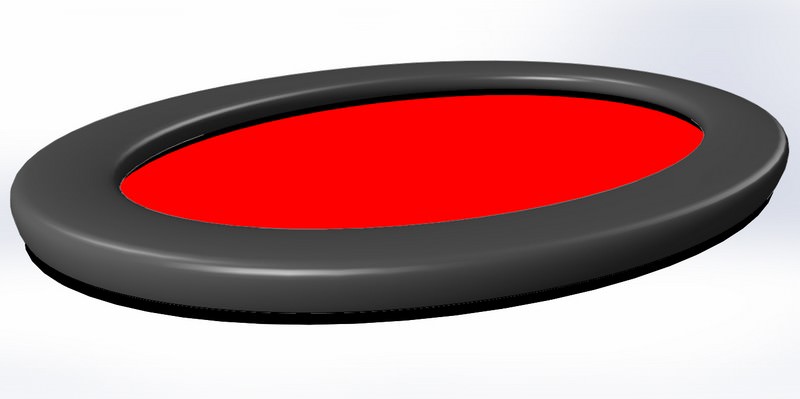
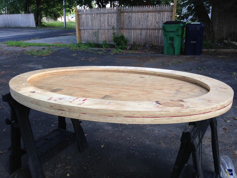
> ellipse shaped - my favorite table design
> 3/4" raised rail because I like the look and ergonomics
> sturdy folding legs - something a bit nicer than standard banquet table legs
> plain SSC / vinyl rail
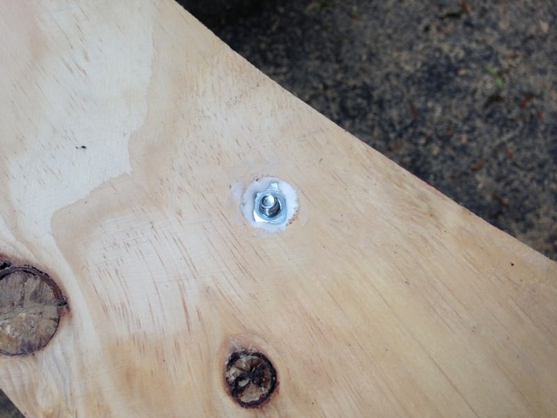
> fully disassemble-able for future layout upgrade and/or rail re-upholstering
> trim ring with decorative nails beneath the rail, for a nice visual touch

Figured it would take me a month or two to complete - here I am in late October just wrapping it up. I've waited til now to post a build thread because - frankly - I've been afraid all along that the result would not be worthy of posting.

Fortunately, it turned out pretty decent given my circumstances.

This build was done in a driveway, 100' from the nearest outlet, with materials transported in a 2-dr coupe, with sub-par tools** lugged down three flights of stairs in a cardboard box for the odd few hours I could squeeze in every weekend.

This thread is intended to provide some inspiration for those who think they may not have the resources to embark on a build. Take your time, execute each step to the best of your ability, learn from the missteps, and stick with it - it can be done!

I made plenty of mistakes in both design and execution along the way and intend to share the wisdom I've gained in realizing them.

So let's dig in.....

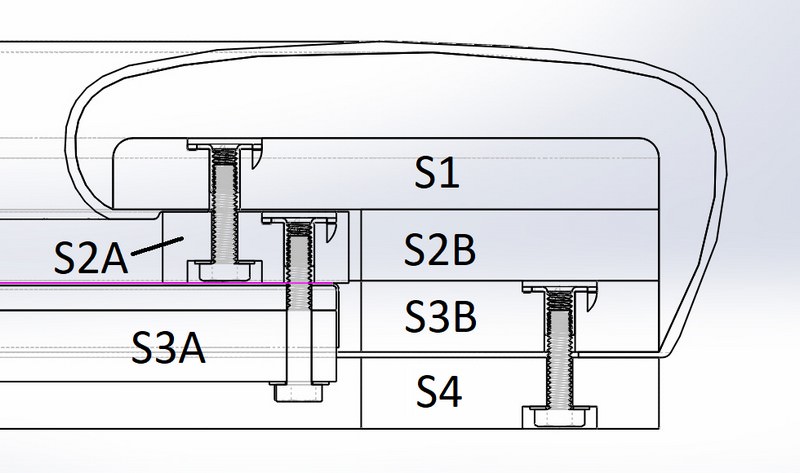
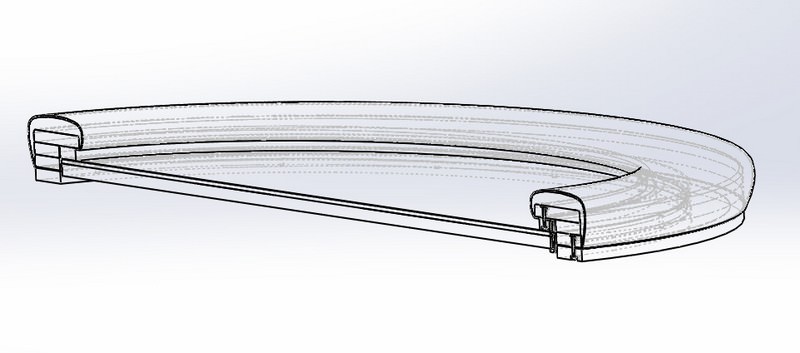
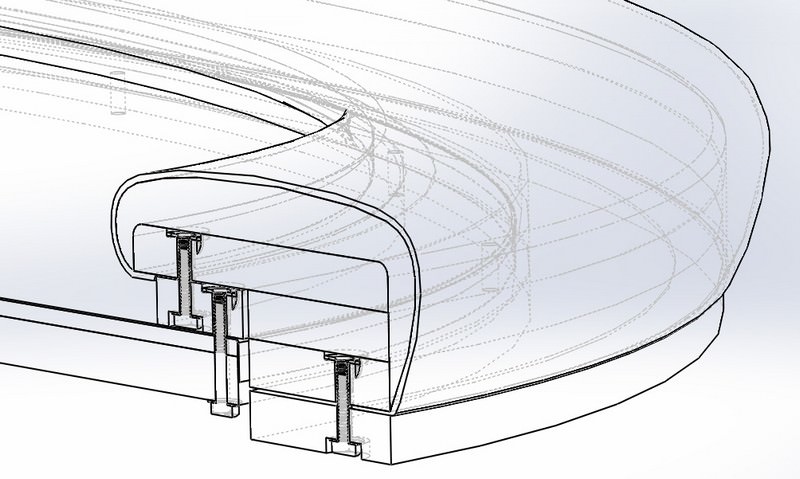
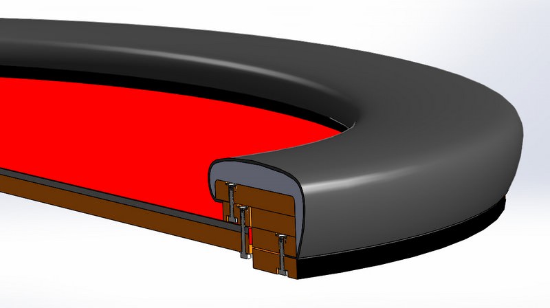
I started with a rough cross section sketch and some calculations for placing the ellipse foci:
ytOm8xs.jpg


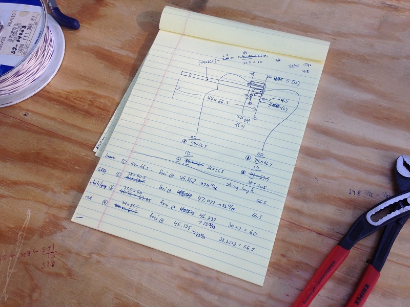
(**Okay, so those Knipex slipjaws are badass. Most of the other tools in this build... not so much.)

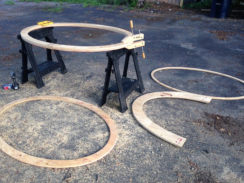
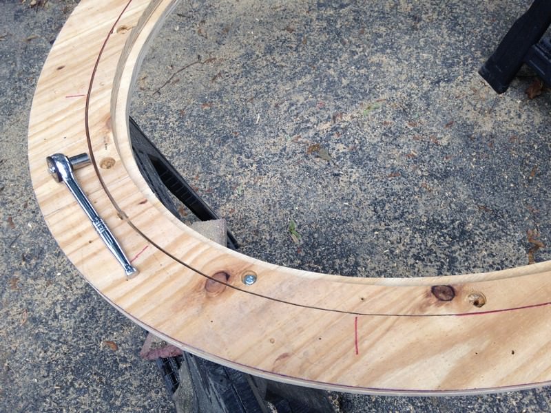
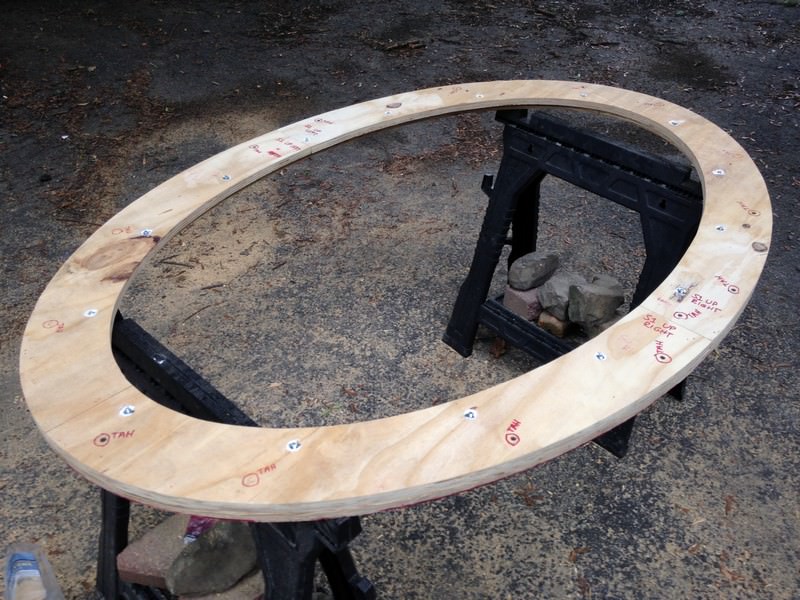
Laying out some ellipses to cut the rail. I had previously rough-cut the plywood to shape so I could shoehorn it into my car. All the plywood I used was free scrap.
kv5KA42.jpg


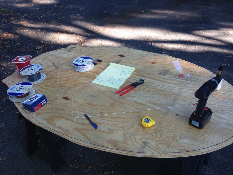
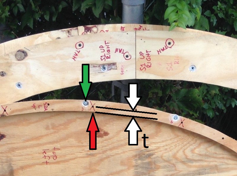
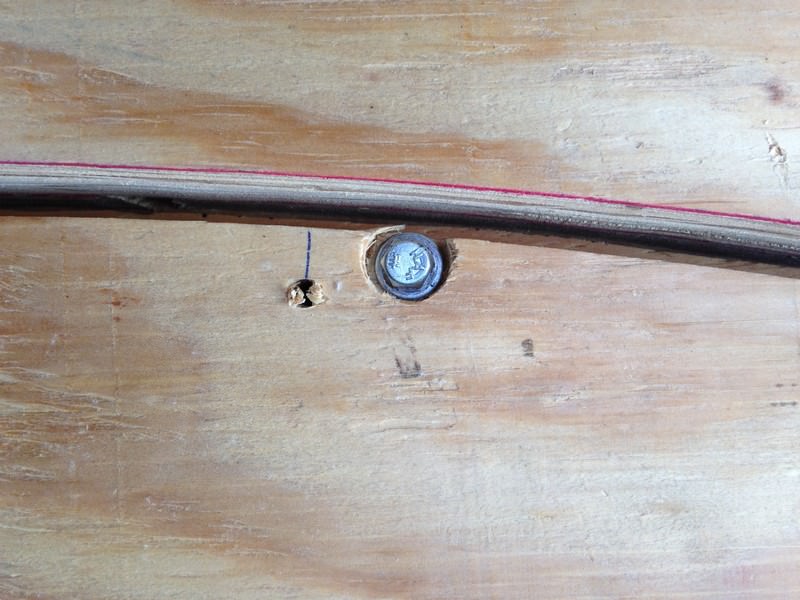
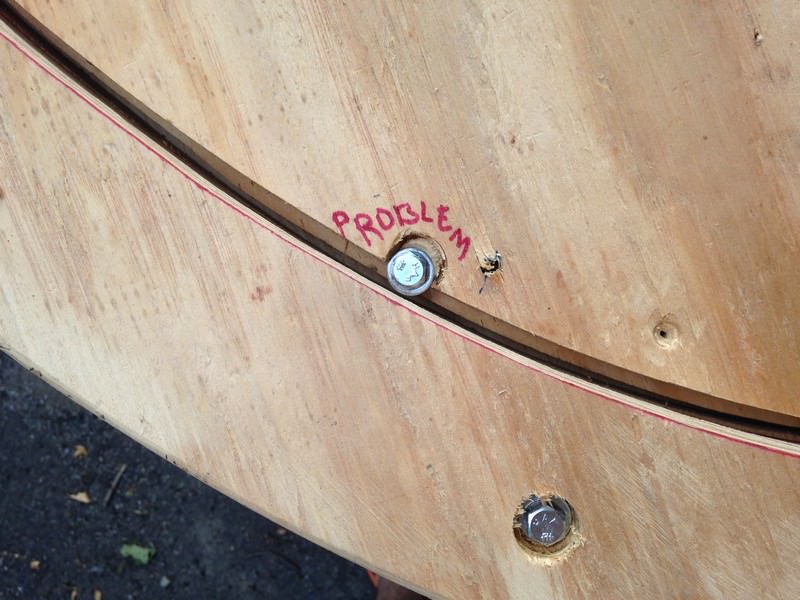
I thought this wire would be pretty resistant to stretching. It wasn't. This caused some asymmetries that would plague me through the whole build.

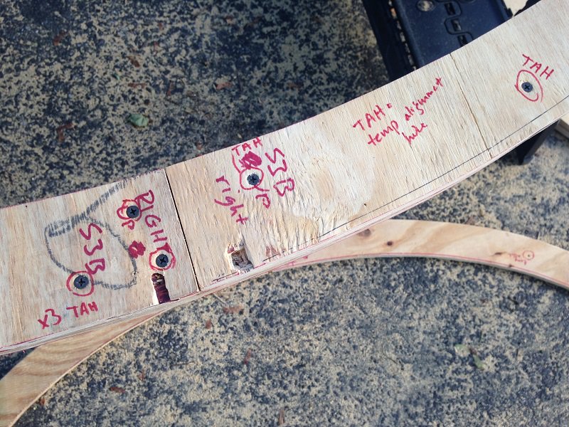
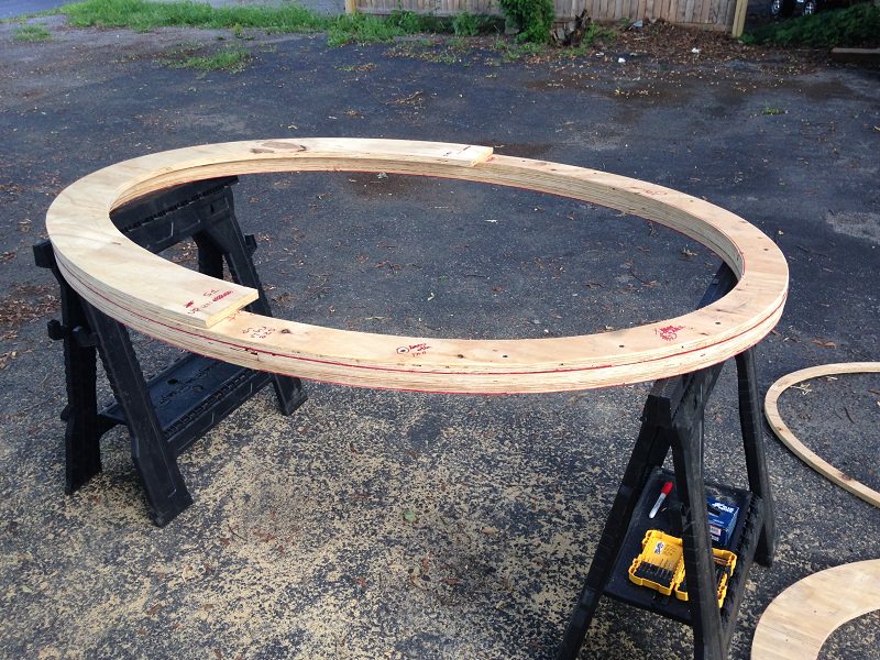
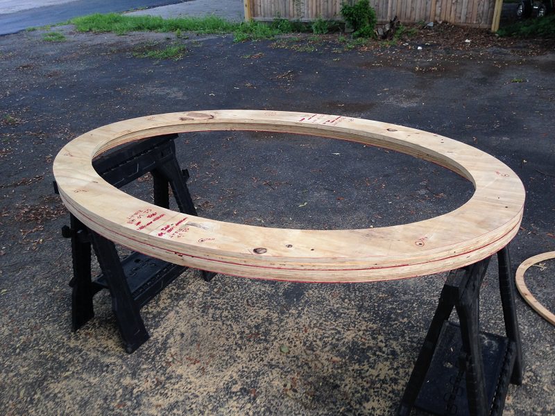
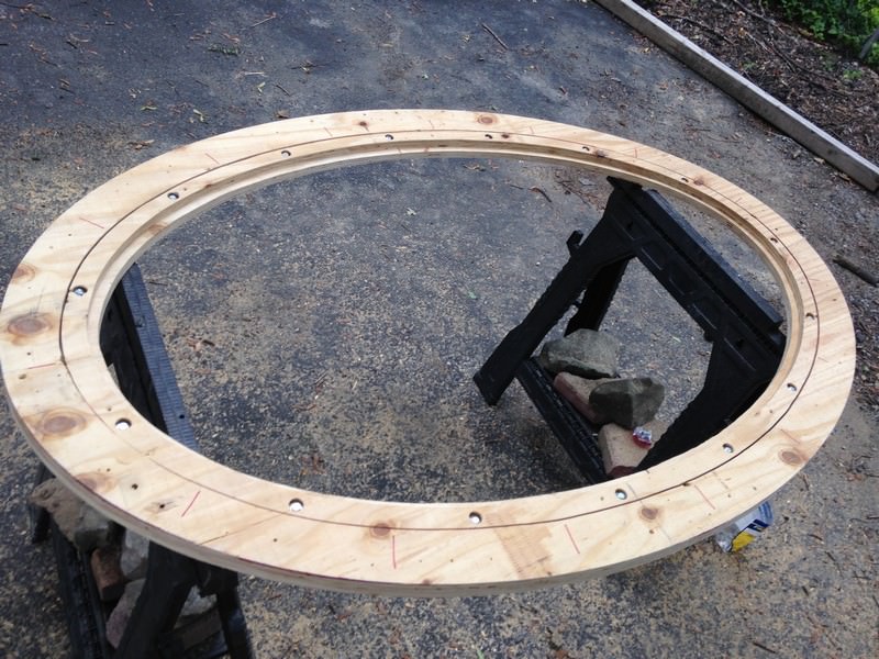
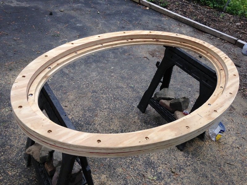
Using the best available jigsaw blades and taking your time on the cuts really helps make up for a shitty jigsaw. Note how I made two cuts to replicate the 1/4" kerf that a router would leave you. This really helped fitting the playing surface to the rail pieces later on.
iqNRzN5.jpg


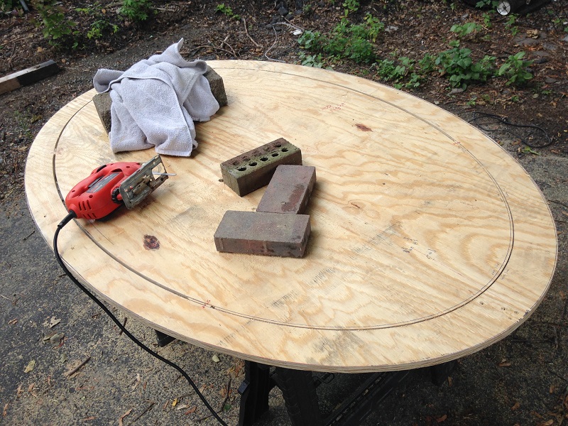
Also note how I left "tabs" connecting segments of cuts. This was a very helpful technique as I was able to make the majority of the cuts without the center piece wanting to drop out and. I cut off the tabs as a last step only after going all the way around with the rest of the cuts.

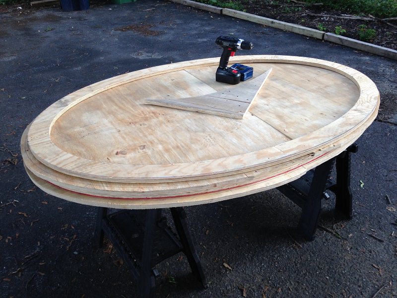
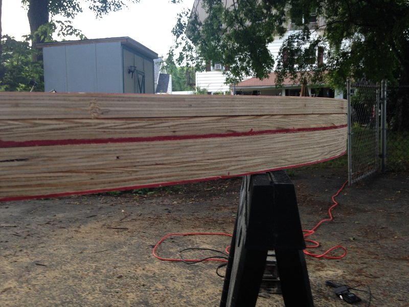
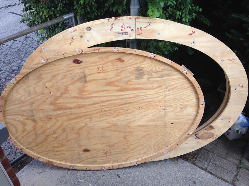
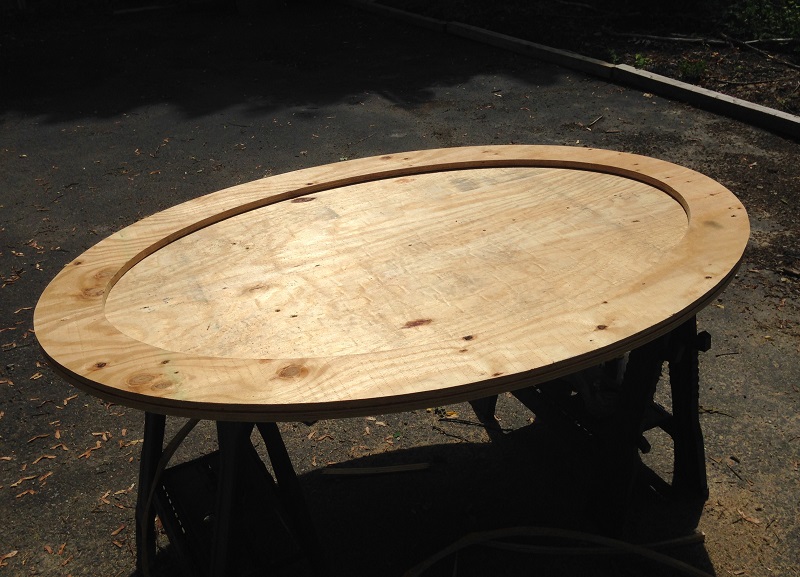
And a few other pieces cut and ready to go. The piece on top is the upper rail surface. Later on I would end up cutting it right in half. o_O
OJTpDAM.jpg


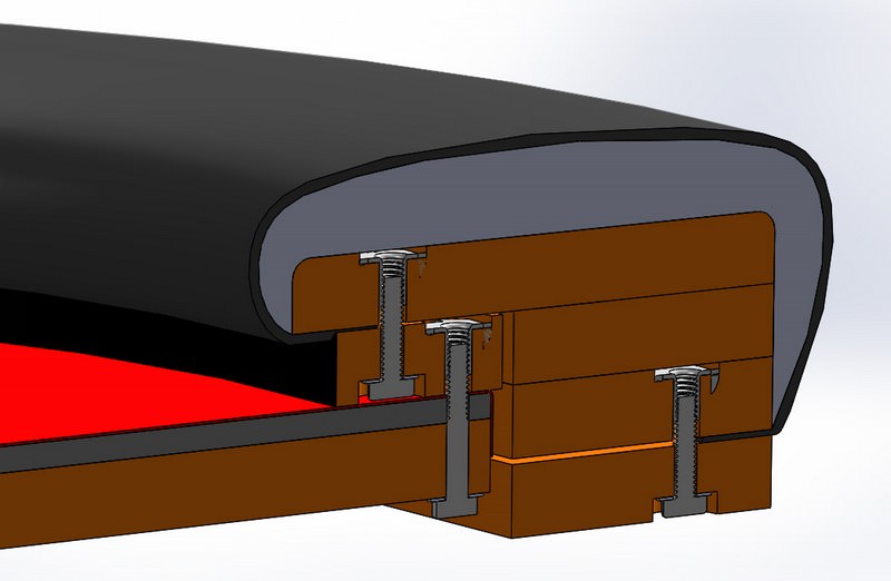
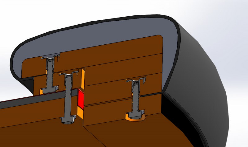
Once I locate all my currently misplaced sketches - I will go through the design and cross section layout in a little more detail so that you can follow along what's what in future pictures. The raised rail added more complexity than I bargain for!
 
Glad to have everyone in here following along!

A slightly comical situation unfolded this morning. A bit of background: The company I work for has been doing very well the last few months and I've put in a lot of extra hours to keep up with the increased sales and growing pains. As a token of appreciation my boss asked if there was any sort of personalized gift the company might buy me. I opted to ask for my table supplies and got the OK. He was curious how the build was progressing, so with his permission I brought the table into work last weekend to do the upholstery. This gave me a bit more space to work in and access to a nice compressor for my nifty new pneumatic stapler. He was impressed with the table and also gave me the go ahead to keep it stored there for the week until I could finish final assembly this weekend.

Last night I figured out that all my build notes must be stashed away along with my tools underneath the table. So it went to grab them this morning, but soon discovered something was terribly, terribly wrong.

The large open doorway to the storage room.... simply wasn't there any more. There was only ... A Wall.

This wall, having appeared so suddenly and without warning, made for quite the surreal situation - as if I had transported to some parallel universe where the doorway never actually existed and my table would be lost to a mysterious rip in the spacetime continuum.

But I'm (mostly) sure this isn't actually the case, and I'll be able to get everything sorted out when I'm back in the office next week.

Anywho. In the meantime, I'll continue on with some build pics instead of illustrating the design/cross-section.

I needed four sheets of ply for my raised rail design, but only had two continuous sheets large enough. So two of the layers in my rail would be cut from split sheets. I had to re-purpose the upper rail piece into another part, and cut out a new (split) upper rail. Laying out the parts from more rough-cut sheets:
vwvllCB.jpg


Lots and lots of cutting............ went through five jigsaw blades!
YOpgPxD.jpg


Lacking enough clamps, I screwed everything together to keep alignment all along. Keeping parts, sides, and holes labeled was crucial!
al0WrtA.jpg


Yes, there are some nasty gouges in that wood. No worries, this will be addressed later...

The rail is taking shape!
hP94NX5.jpg


The cuts came out pretty decent - but it was time to break out the belt sander. At this point I had NO IDEA how much sanding lay ahead of me...
DqA7ZgZ.jpg


Shuffle up and deal, baby! Ok, not quite yet.
rAcv1OB.jpg


Just looking at this picture makes my hand and back start hurting again.
guwvMbx.jpg


Three of these four layers will be upholstered. The bottom one (on top in this picture above) is the trim/decorative nail ring for below the upholstered rail. So who can identify the single MASSIVE mistake I made in the design?
 
I've never built a raised rail table before but I would think you'd want to upholster the rail before you attached the bottom layer for the decorative nail ring.

**Edit: After further review, it looks like you need the decorative nail layer to be cut narrower so that the rail riser sits on the playing surface and the decorative layer covers the outside edge of the playing surface.
 
Last edited:
You left a giant elliptical hole where the felt should be and now all the cards and chips just fall to the floor?
:ROFL: :ROFLMAO:

I do sort of regret not installing cup holders, but this is a more fundamental design issue.

I've never built a raised rail table before but I would think you'd want to upholster the rail before you attached the bottom layer for the decorative nail ring.
That definitely would be an issue, but it's just temporarily attached in these pictures so I could sand all the pieces together.

**Edit: After further review, it looks like you need the decorative nail layer to be cut narrower so that the rail riser sits on the playing surface and the decorative layer covers the outside edge of the playing surface.
Close! The decorative nail layer will successfully cover the outer edge of the playing surface, but the width width of it, and of the other matching pieces inside the rail, is exactly what will become problematic.
 
I'm guessing that the playing surface fits inside the decorative nail layer and the matching pieces inside the rail so that the upper layer of the rail sits directly on the playing surface. So basically not having a raised rail?
 
Yes...playing surface fits inside that stack of 3. But the upper layer of the rail is offset from the playing surface by another layer of ply that also fits inside the rail stack... that's the thin ring on the ground in the second pic of the last set of pics.

That ring should have been thicker.
 
Don't you want the risers flush with the covered rail? To do that, the interior edge would need to meet up.

The way you have it, the covered rail will stick out, creating a small recess between the covered rail and the playing surface.
 
Yes the riser layer is radially recessed from the covered rail by about 1/2". This was intentional, I could have made it flush, but thought it would look good this way. Kind of gives the effect that the rail is "floating" - no complaints in the finished product.
 
Lots and lots of cutting............ went through five jigsaw blades!
Never skimp on jigsaw blades. A cheap jigsaw with quality blades is better than an expensive jigsaw with cheap blades.
 
Yes the riser layer is radially recessed from the covered rail by about 1/2". This was intentional, I could have made it flush, but thought it would look good this way. Kind of gives the effect that the rail is "floating" - no complaints in the finished product.

Obviously, its what you want, not what I want, but.

1. This pic looks like a whole lot more than a 0.5" recess.

guwvMbx.jpg


2. Do you have plans for covering the inside of the riser (as opposed to leaving it as three sandwiched layers of plywood)?

EDIT:

3. Your ellipse is much more rounded than mine (which is more pointy on the ends). I like it. What were the measurements for the foci (the location of the nails that you used to get your outer edge)?
 
Never skimp on jigsaw blades. A cheap jigsaw with quality blades is better than an expensive jigsaw with cheap blades.
Absolutely true. I used Bosch blades and was impressed. Just erred on the side of switching them out frequently since I already had the 5pk.

Other jigsaw advice: Power cord management - plan it out in advance so you can focus 100% on the cut and not get snagged up. Seems silly but makes a big difference.

And patience. If you find yourself off by a quarter blade width .... Probably time to take a break a pick it up later.
 
Last edited:
@WedgeRock that pic is just the rail, no riser there. The thin oval on the ground in the second pic fits inside there against the top rail surface. And brings the offset to 1/2" between rail & riser. It's only a 3/4" height raise (single ply)

I'll get sketches posted eventually and it will make everything much clearer. This is why I'm bummed to not have my notebook..., wanted to post up all the exact dimensions which I don't know in my head.

The small table and standard width do make for a pleasing ellipse proportion imo. If you search an ellipse calculator for 67 major axis and 44 minor axis it will spit out the foci.
 
I modeled the table so you can understand the cross section and follow along a little better with the photos. The exact proportions may be slightly off, but it's close. Left out some details like the trim nails and only put in one set of bolts, because I ran out of time.

The S3A-to-S2A and S2A-to-S1 bolts will be staggered and won't actually exist in the same section, I put them in a single section for illustration purposes only. S3A is the playing surface and the layer above it is the foam.


EkCHcf6.jpg


weYSR7S.jpg


fxR9tY2.jpg


xzTmg8e.jpg


UQSNepl.jpg


Xo2MoNu.jpg


sP24WK3.jpg


2. Do you have plans for covering the inside of the riser (as opposed to leaving it as three sandwiched layers of plywood)?
Original plan was for stained edgebanding but I ended up just giving them eight coats of black lacquer, wet-sanded between coats.
 
It should be very comfortable for 6-7 and 8 could probably squeeze in. I don't have the room to host any bigger than this right now, so it should be a good fit.
 
I modeled the table so you can understand the cross section and follow along a little better with the photos. The exact proportions may be slightly off, but it's close. Left out some details like the trim nails and only put in one set of bolts, because I ran out of time.

The S3A-to-S2A and S2A-to-S1 bolts will be staggered and won't actually exist in the same section, I put them in a single section for illustration purposes only. S3A is the playing surface and the layer above it is the foam.


EkCHcf6.jpg


weYSR7S.jpg


fxR9tY2.jpg


xzTmg8e.jpg


UQSNepl.jpg


Xo2MoNu.jpg


sP24WK3.jpg


Original plan was for stained edgebanding but I ended up just giving them eight coats of black lacquer, wet-sanded between coats.
Impressive skills. Thank you for sharing your thoughts and especially for these illustrations. (y) :thumbsup:

Questions (mainly because I will finally be tackling my table build very soon):
1. Can sheets S2A & S2B be the same sheet?
2. Can you sandwich sheets S1, S2A & S3A with one long bolt? Just curious as to reason for the 2 bolts?
 
Last edited:
Thanks! & you're welcome!

1. Yes, the S# is "sheet #" so four total sheets with S2A/S2B from one and S3A/S3B from one.

2. Sure you could make that connection as one bolted sandwich. My design kind of evolved on-the-fly and just ended up like that. But also, I tend to have issues fitting things together when layering multiple hand-drilled parts with clearance hole alignment.
 
  • Like
Reactions: 72o
Thanks! & you're welcome!

1. Yes, the S# is "sheet #" so four total sheets with S2A/S2B from one and S3A/S3B from one.

2. Sure you could make that connection as one bolted sandwich. My design kind of evolved on-the-fly and just ended up like that. But also, I tend to have issues fitting things together when layering multiple hand-drilled parts with clearance hole alignment.
Thank you for the response.

For my first question above, I guess I should have worded as can they be the same piece? Meaning is there a reason why you show it as 2 separate pieces from the same sheet?
 
Ah, gotcha. If you look closely at the very first pic in OP you see I originally had it planned that way. But I made them separate so that I could upholster the rail onto the wider ledge of S1, then bolt on the riser (S2A) to hide the staples and cut edge of the rail fabric. S2B is encapsulated within the rail and its upholstery.
 
  • Like
Reactions: 72o
Ah, gotcha. If you look closely at the very first pic in OP you see I originally had it planned that way. But I made them separate so that I could upholster the rail onto the wider ledge of S1, then bolt on the riser (S2A) to hide the staples and cut edge of the rail fabric. S2B is encapsulated within the rail and its upholstery.
Awesome. Yup that makes total sense now. Great tip.
 
Alright, sorry for the delay - been very busy, but let's dive back in.

Time to drill some holes! I started with the S2A-to-S1 connection. 1/4" thru holes, 3/4" spade bit for counterbores to sink bolt heads. Remember to pilot with a small bit thru, THEN counterbore, THEN open up to 1/4" thru.

QNERj61.jpg


Top of S1 with a shallower counterbore so the T-nuts would sit just below flush. Glued in the T-nuts with some heavy duty construction adhesive. Tightened in a bolt to pull the T-nut prongs securely into the wood & let it dry for a couple days. This bolt is too long; I would have to pick up some shorter ones that wouldn't protrude above the top rail surface.

6imFf3x.jpg


Repeat x15. Bolts were space roughly 10" apart IIRC:

n8HyZXH.jpg


Opposite side:

Oql7TOc.jpg


Next up, the S4-to-S3B connection. Same procedure, same bolt spacing, 17x bolts. This is one of my favorite pictures of the build.

uxG4euy.jpg


Now time for the S3A-to-S2A bolts. This is where my design error revealed itself. The S3A (riser) piece is very narrow in cross-sectional width. This narrow width is all the covers the the bolt holes that go through the playing surface, foam, and cloth. After cutting a hole in the cloth, it has to be reinforced with some staples around the hole, to prevent tear-out. These staples will compress the foam and leave a little indentation that also has to be covered by the riser.

Originally I centered these bolt holes on the cross sectional width of the riser. But I then realized that would position them too far away from the edge of the playing surface and risk exposing the stapled foam indentation mentioned above. So I repositioned the holes to the very extreme outside edge of the playing surface. Didn't manage to get any pics while working this all out, but here are the finished pieces:

S1JK2Mj.jpg


Okay that's not very illustrative. Enhance!! Enhance!! Enhance!!

pF9oafj.jpg


Red arrow = original location. Green arrow = corrected location. t = thickness of "coverage" that I feared would leave visible imperfections on playing surface.
If I did this again, I would swap the cross sectional widths of S2A vs {S2B, S3B & S4}.

So about those holes very close to the edge of the tabletop. First point: I counterbored these as well, which is not shown in the model/drawings in previous post. Second point: most of them worked out okay, like this one:

ZM5g5FF.jpg


However, a few of them got too close to the edge, busted out the sidewall of the hole, and allowed the bolt to creep out of the hole. Bloody hell.

xA7KbxE.jpg


So what did I do? Squat! They worked fine, just like that. :D No harm, no foul... but lesson learned.

All the basic woodworking is now complete and the pieces can be fitted together. Starting to look like a table!

CoOmRLc.jpg


In the next installment we'll be getting all the parts ready for upholstery with lots of wood filler and sanding.
 

Create an account or login to comment

You must be a member in order to leave a comment

Create account

Create an account and join our community. It's easy!

Log in

Already have an account? Log in here.

Back
Top Bottom